In the realm of industrial air filtration, the Pulse Jet Valve (also known as a diaphragm valve) serves as the critical “heartbeat” of a dust collector system. Whether in cement plants, chemical processing, or woodworking facilities, these valves are responsible for maintaining the permeability of filter bags by delivering high-energy bursts of compressed air. Understanding the intricate mechanical balance of these components is essential for optimizing system performance and ensuring environmental compliance.
Part I: Detailed Component Decomposition and Functionality
A pulse jet valve is not a singular mechanical piece but an assembly of precision-engineered components designed to withstand millions of cycles under high pressure. Below is a breakdown of each primary component and its specific role.
1. The Valve Body and Cover (Housing)
-
Material: Usually high-quality die-cast aluminum or stainless steel.
-
Function: The housing provides the structural integrity required to contain high-pressure compressed air (typically 0.3 to 0.6 MPa). It is designed with aerodynamic internal flow paths to minimize pressure drop during the pulse, ensuring the maximum force of air reaches the blowpipe.
2. The Main Diaphragm (The Kinetic Core)
-
Material: High-performance elastomers such as Nitrile (Buna-N), Viton (for high temperatures), or specialized TPE.
-
Function: This is the primary moving part. It acts as the physical barrier between the compressed air inlet and the outlet. Its flexibility allows it to lift and reseal instantaneously. A high-quality diaphragm must possess excellent tensile strength and fatigue resistance to endure the rapid “snapping” motion.
3. The Solenoid Pilot Operator (The Brain)
-
Components: Includes the electromagnetic coil, the plunger (armature), and the spring.
-
Function: This is the electromechanical interface. When an electrical signal is received from the pulse controller, the coil creates a magnetic field that lifts the plunger. This action opens a small “pilot” orifice, triggering the chain reaction that opens the main valve.
4. The Spring
-
Material: Stainless steel or carbon steel.
-
Function: Located in the rear chamber, the spring provides the mechanical force necessary to push the diaphragm back into the sealed position once the electrical signal terminates. It ensures a crisp, clean shut-off to prevent air wastage.
5. The Bleed Hole (Orifice)
-
Function: A tiny, precision-drilled hole in the diaphragm or valve body. It allows compressed air to travel from the inlet to the rear chamber. This creates the pressure equilibrium necessary to keep the valve closed during its “off” cycle.
6. The Pilot Exhaust Port
-
Function: This is the exit point for the air trapped in the rear chamber. When the solenoid opens, this port allows the pressure to vent to the atmosphere, creating the pressure drop required for the diaphragm to lift.
Part II: The Physics of Operation – A Step-by-Step Analysis
The operation of a pulse jet valve is a sophisticated exercise in differential pressure dynamics. It relies on the fact that air pressure applied over a larger surface area creates a greater force than the same pressure applied over a smaller area.
Phase 1: The Closed (Standby) State
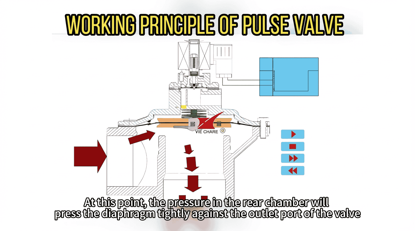
In its default state, the solenoid is de-energized. Compressed air from the header tank enters the valve’s inlet. A small portion of this air passes through the bleed hole into the rear chamber (the space above the diaphragm). Because the surface area of the diaphragm inside the rear chamber is larger than the area exposed to the inlet pressure, the resulting force pushes the diaphragm downward against the valve seat. This creates a leak-proof seal. At this stage, the system is in a state of high-pressure equilibrium.
Phase 2: Actuation and Pilot Venting
When the cleaning cycle timer sends an electrical pulse (typically 50ms to 150ms) to the solenoid coil, a magnetic field is generated. This field pulls the plunger upward, uncovering the pilot exhaust port. The compressed air trapped in the rear chamber is exhausted to the atmosphere much faster than it can be replenished through the tiny bleed hole. This causes an immediate and localized drop in pressure in the rear chamber.
Phase 3: The Pulse (Main Discharge)
The sudden loss of pressure in the rear chamber creates a massive pressure differential. The high-pressure air at the inlet now exerts a force much greater than the remaining pressure in the rear chamber. The diaphragm is forced upward instantaneously. This opens the main orifice of the valve, allowing a high-velocity “slug” of compressed air to discharge into the blowpipe. This air creates a shockwave down the filter bag, flexing the fabric and dislodging the dust cake.
Phase 4: Resealing and Recovery
As soon as the electrical signal to the solenoid ends, the spring pushes the plunger back down, sealing the pilot exhaust port. Compressed air begins to refill the rear chamber through the bleed hole. As the pressure builds back up, the force once again overcomes the inlet pressure, pushing the diaphragm back onto the seat. The valve is now ready for its next cycle.
Part III: Visual Demonstration and Dynamic Analysis
To truly grasp the millisecond-level interaction between the solenoid, the air chambers, and the diaphragm, visual aids are indispensable. The following video provides a high-speed look at the internal mechanics, demonstrating how these pressure shifts translate into physical motion.
Technical Note: Observe the rapid evacuation of the rear chamber in the animation. This specific sequence is what determines the “crispness” of the pulse. A sluggish valve results in wasted compressed air and poor cleaning efficiency.
Part IV: Factors Affecting Performance and Efficiency
To achieve a 2000-word level of technical proficiency, one must look beyond basic operation and consider the variables that dictate industrial success.
1. Pulse Duration (On-Time)
If the pulse is too short, the shockwave won’t reach the bottom of the filter bag. If it is too long, you are simply wasting expensive compressed air without adding any cleaning value. The ideal “on-time” is usually when the valve achieves its full lift and begins to close immediately after the shockwave is generated.
2. Header Tank Pressure
The valve’s performance is intrinsically linked to the air supply. If the header tank is too small or the pressure is too low, the “peak pressure” of the pulse will drop, leading to ineffective cleaning and “blinding” of the filter bags.
3. Environmental Conditions
-
Cold Climates: Moisture in compressed air can freeze, jamming the pilot plunger. This requires the use of heaters or ultra-dry air.
-
High Temperatures: In industries like smelting, diaphragms must be made of Viton to prevent the rubber from becoming brittle or melting.
4. Maintenance Indicators
A failing pulse jet valve usually presents in two ways:
-
The “Hiss”: A continuous leak, indicating a ruptured diaphragm or a piece of debris stuck in the seat.
-
The “Thud”: A weak pulse, indicating a clogged bleed hole or a failing solenoid coil.
Part V: Conclusion
The pulse jet valve is a masterpiece of industrial engineering, utilizing the laws of fluid dynamics to perform a violent yet controlled mechanical task millions of times over its lifespan. By understanding the role of each component—from the microscopic bleed hole to the heavy-duty diaphragm—operators can significantly extend the life of their dust collection systems and reduce operational costs.
Proper selection, installation, and monitoring of these valves ensure that the “heartbeat” of the plant remains steady, keeping the air clean and the machinery running at peak performance.